We remain fully operational. Our teams are working around the clock to ensure your deliveries continue safely.

DOWNLOAD THE APP


Copyright © 2025 Desertcart Holdings Limited
DOWNLOAD THE APP
![D-Planet [4-Pack] 5A DC-DC Adjustable Buck Converter 4~38v to 1.25-36v Step Down Power Supply High Efficiency Voltage Regulator Module](https://m.media-amazon.com/images/I/71hsjeaahRL._AC_SL3840_.jpg)
Buy anything from 5,000+ international stores. One checkout price. No surprise fees. Join 2M+ shoppers on Desertcart.
Desertcart purchases this item on your behalf and handles shipping, customs, and support to South Korea.
⚡ Power up smart, stay cool, and never miss a beat!
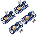
The D-Planet 4-Pack 5A DC-DC Adjustable Buck Converters deliver high-efficiency (up to 96%) step-down voltage regulation from 4-38V input to a finely tunable 1.25-36V output. Each compact module supports up to 5A current with built-in protections against overheating, short circuits, and reverse voltage, making them ideal for professional-grade electronics projects, battery management, and power supply customization. Trusted by makers and engineers alike, these modules combine precision, safety, and versatility in a sleek PCB-mount form factor.
| ASIN | B079N9BFZC |
| Best Sellers Rank | #108,853 in Tools & Home Improvement ( See Top 100 in Tools & Home Improvement ) #399 in Power Converters |
| Brand | dkplnt |
| Brand Name | dkplnt |
| Current Rating | 5 Amps |
| Customer Reviews | 4.2 out of 5 stars 424 Reviews |
| Item Weight | 16 Grams |
| Manufacturer | D-PLANET |
| Maximum Frequency | 180 KHz |
| Minimum Frequency | 180 KHz |
| Model | 5864305253 |
| Mounting Type | PCB Mount |
| Part Number | 4 |
| Power Source | Dc Powered |
| Specification Met | CE, RoHS, UL |
| UPC | 721968030648 |
C**T
Great value, easy to setup, voltage drifts a little bit as load increases.
I'm building an Arduino-based lithium battery charging rig, mostly for fun and learning, but also so that I can recycle old laptop batteries into solar power storage. I'm using these buck converters to step 12v supply down to 5v for powering TP4056 charge controller boards that charge 18650 batteries. Each of the 'battery modules' in the picture handles 4 batteries, and could draw up to 20 watts. So putting one of these buck converters on each module lets me distribute power at 12v instead of 5v, significantly reducing current flow, wire size, and voltage drop. The output voltage of the buck converter stays fairly steady, but it does drop as load increases. Adjusting the output voltage is straightforward, but make sure you turn the pot down before connecting anything. The units ship with the pot adjusted to full output voltage! With 12v input, and adjusted to 5v output with no load, here are the drops I saw as load was applied: 0.0a - 5.0v 0.5a - 4.93 1a - 4.86v 2a - 4.70v 3a - 4.55v Abruptly disconnecting the 3a load, voltage returned to the initial 5v setting. Using the 'max' function of my multimeter, I did not see any spike or overcorrection. These work really well for making a big step down ahead of anything that uses a linear regulator for final voltage regulation. The closer you can tune these to the final voltage you need for the anticipated load, the less energy the linear regulator will need to dissipate. From my measurements, these appear to use a common ground. So the negative output isn't really necessary as it is the same as the negative input. These are great little devices, with lots of uses. Definitely recommended.
C**S
They work!
I just received these today. Bearing in mind that the seller offers a refund for any non-functional units, I tested them all right away to see if any were DOA. None were! I'll update if any fail in use. They're pretty nice units overall, based on XLSEMI's XL4015 chip. The circuit seems to be pretty much straight out of the datasheet's application notes, with the exception that the output capacitor is 220uF instead of 330uF as suggested on the datasheet. The boards all appear clean, undamaged, and well soldered. In testing, their output regulation versus load and input voltage seems excellent. Output voltage remained solid at 5.0V from ~9-14V input voltage and 0-0.5A output current. At 0.5A, only the toroidal inductor got vaguely warm. All other components remained cool to the touch after several minutes, even without installing the included heat sink. Low current efficiency isn't great, but that's to be expected. Even at ~9V in, 5V @ 51mA out, though, I measured just short of 70% efficiency, which saves about 10mA current drain versus a linear regulator. A simple modification to slightly boost low current performance would be to remove the power LED from the board. At 5V out, I measured a current consumption of 0.65mA by the LED. The only downside? I didn't get the pictured standoffs. It's a minor complaint, as I'm probably not going to be using them, but it would have been nice to receive everything as pictured. --- In case it's of any use to anybody, here's a summary of the notes I took while testing all four units. It's not a broad battery of tests, since I mostly just wanted to make sure they'd work in my lower-current application, but maybe they'll be of use to someone. Results: No load output voltage: 5.00V, 5.00V, 5.00V, 5.00V 10 ohm load output voltage: 4.99V, 5.00V, 5.00V, 5.00V No load input current (@13.6V): 5.0mA, 4.9mA, 4.8mA, 4.6mA 10 ohm load input current (@13.6V): 210mA, 220mA, 210mA, 210mA Average efficiency: 86.5% Additional efficiency testing on one unit only: With 97.7 ohm load and output set to 5.00V (51.1mA out): 13.6V in: 31.4mA draw, 59.9% efficiency 8.84V in: 41.6mA draw, 69.6% efficiency LED current consumption: 0.65mA (3.32V across 5.1k resistor)
J**N
Working well so far!
I'm using one of these in a custom light setup, converting down from a 20v Porter Cable battery pack to 12v. These seem to work pretty well so far. The mounting holes are oddly placed, but I'm attaching a pic of the dimensions in case you want to 3d print your own tray or mounting enclosure.
E**N
Got the 4-Pack, All 4 Good! Use for vacuum tube DC filament voltage regulator.
These seem to be a good value for the money, definitely cheaper and smaller than I could make myself. My application is as a DC filament voltage regulator in a vacuum tube audio amplifier. Each one of them was in a sealed gray smoke ESD bag, then those 4 were inside a larger gray smoke ESD bag (also sealed). This larger outer bag was wrapped in several layers of 1/4" bubble wrap, and then placed in a bubble envelope (that fit inside my cluster mailbox along with a copious amount of junk mail). So 5-Stars on packaging. I tested all 4 of them soon after opening the box they came in. I really needed only one at this time, but I couldn't pass up the discount on buying the 4-pack, as I know I'll use them real soon in other projects I have planned. As per other reviewers have said, I first turned the trim-pots counter-clockwise 10 revolutions on each one of them. Then one-by-one I hooked them up to a 0-28V 7.5A power supply, monitored the output on a calibrated Fluke 77BN multimeter, and I attached one of those Golden Metal-Fin(chassis mount) 10-ohm 25-W power resistor as a load (resulting in a 0.63A current being supplied by the little module) and this was a good test for my immediate application because I'll be using it on a tube that draws 0.6A at 6.3V for it's filament power. Each one when fired up with a 12V input, was putting out around 1.357volts with the trim-pot adjusted counter clockwise, so in that manner they were all identical. I then adjusted the trim-pot until I saw 6.3VDC on the Fluke multimeter. Then I changed the input voltage to 9V, and no change in the output. Then I changed the input voltage to 5V, and STILL no change in the 6.3V output under load! So these things, while sold as "DC-DC Buck Converters" can actually boost as well, at least from 5V input to 6.3V output as I tested them. Bonus happiness, so 5-Stars for that too. (I have forgotten to mention that on each of the 4 modules, I stuck the little heat-sink supplied onto each regulator chip before I began testing). Also I checked to see if the 6.3V output voltage would change if I removed the load resistor while the input voltage was applied; the answer is NO, not even by 1mV did the output change, regardless if the input voltage was 5, 9, or 12V, removing and inserting the load resistor had no effect on output voltage at all. So very stable, 5-Stars again. Since I was doing this testing at work, I had all day to test them, so after initially testing all 4 as described, I did a "burn-in" test for 2 hours on each one. The PCB itself (by touching the ground-plane on the back of the board, and the regulating chip's heat-sink were just barely perceptibly warmer than my finger's skin temperature after operating under load for 2 hours. The little toroid core (or the wire wrapped around it) WAS a bit warm after the 2-hour burn-in time, but not so warm as to make me want to withdraw my finger. But definitely warmer that the PCB board or the regulator chip. I can live with that. Next, I did what I had drawn in my schematic for my amplifier, which was place a 1,000uF 50V electrolytic cap across the output, along with a .01uF ceramic disc capacitor. (in my schematic I drew the electrolytic capacitor being right on the output of the module, and then a .01uF capacitor being right on the tube socket's filament pins). This being done, I hooked up a X1 probe to the load resistor and looked at ripple on a calibrated Tektronix 2246 Oscilloscope; ripple was basically nil with these two capacitor filters on the output (less than 0.5mV). So I'm satisfied that these will be quite useful for a DC Filament Regulator in my vacuum tube audio projects, and far superior to the LM338 5-Amp Linear regulator because of the much lower heat output - it's really orders of magnitude less heat than I got from the LM338 linear filament voltage regulators I have used in the past. So for my application, again 5-Stars. For those of you who don't think in "Metric" and whom are too lazy to open up another tab in their browsers to make use of a free Length Calculator, here are the dimensions: 2.125" L x 1.0"W x 0.625"H. Finally, I get so tired of so many of these Chinese products that claim you can use them (for example) at up to 32V input voltage BUT they only give you 35V-rated capacitors on the board. That's just piss-poor engineering, if they have 35V-rated capacitors, you'd best not be applying more than 24V or so (in order to have a comfortable margin of error. I am most PLEASED to tell you that both the input and output capacitors on this PCB are rated at 50V. One last, well deserved 5-Stars! I can't say how they'd perform at the full 5A load, because I didn't have the load resistors to do that. But on the other hand, in keeping with good engineering practice, I don't think I'd ask more than 2A (2.5A on a dare) out of these. You should never expect to get away with (long term) running any device at it's maximum current or voltage rating. I'm going to go ahead and use one of these in my current project, which is a metal box 8" x 8" x 8" (Hammond 1401E steel chassis with easy-to-machine aluminum front and rear panels) that has a mono 3.8W RMS all-triode Push-Pull amplifier in it driving a front-panel mounted Visaton FR8WP 3.3" Full-Range Driver 8 Ohm Speaker. There will be one of those handy front panel-mounted MP3/FLAC player modules, a volume and tone control - also a "Blend" control, that will allow me to continuously adjust the mix-down of left and right channel inputs to mono, so I can choose all left, all right, or a mix of both for my mono signal (depending or what sounds best with any particular source material). It uses a 12-Pin Compactron 6AC10 (3 hi-mu triodes in one envelope) for an SRPP pre-amp and the transformer (Hammond 125D) driven phase inverter ; and a 9-Pin 5687 dual twin med-mu triode for the push-pull output stage (Hammond 125H output transformer PRI=10K SEC=8 ohm). With 300V going to the 5687 you get a clean 3.8W maximum output from one tube. Step down the 300V to 260V for the phase inverter (with a 1N5311-1 constant current diode in the cathode), and step the 260V down to 240V for the SRPP pre-amp (with a 1N5311-1 constant current diode in the cathode). Total Hi-Fi it will not be, but that's not the application. It will be an 8" cube that lets me listen to audio books and Holy Qur'an readings. So in that application, the transformer's 150HZ to 15KHZ ratings match nicely with the speaker's 100HZ to 20KHZrating. Likewise the 3.8W output is a reasonable match to the speakers 15W maximum power limit, and the speakers 84db/1W/M sensitivity will make it plenty load enough for recliner side-table or bedroom end table listening. In fact, it'll probably also be plenty loud to fill a small room (8' x 8' or so) with sound loud enough to make conversation in a normal voice not possible. I'm going to use just one of these regulator modules for BOTH tube's filaments, that will be 1.5A of current drawn thru the device - comfortably within it's 5A rating. The way I'm going to mount this module is probably the way you ought to do so as well: it'll be mounted on a side or back wall of the enclosure with the trim-pot down and little heat-sink up. This way the module can cool naturally by convection, and the hot air rising will not be heating up the trim-pot (which is plastic and prone to melt or fail. Not that I anticipate (based on today's testing) that it will generate much heat, but better to plan ahead and be safe rather than sorry, no? This mounting attitude also allows airflow to rise across the module's rear ground plane (which radiates some of the regulator's heat). One final note, the two mounting holes in the module accommodate #4-40 hardware, but unless you have a low-profile nut for the top, you'd better use nylon nut there because it's rather close to the input and output solder tabs on the PCB's top. On the bottom, the mounting holes are surrounded by ground plane, so no worries there if you use metal stand-offs, nothing to short on the bottom.
G**R
These little Buck converters are great. Update.
4 received... 4 worked fine. Connected to a 19.8 volt source (in this case an E6440 laptop power supply). The idea is to run a couple of external hard drives using a tap from the PS brick, to eliminate plugging in 2 wall warts and associated lead wires. To test these little beauties the output was set to 12V (actually 12.07V) with a 6 Ohm 50W load. Output variance was about 100 mv when connected but returning to 12.07 within about 500ms, and staying there for the 3 minute test. I would have gone longer but the load resisters were getting pretty hot. As expected from an SMPS there was virtually no heat generated by the board/controller IC. Since the wall warts are only 1.5A my 2A test should suffice. I might try to see how far I can push these in the future, but 2A is fine for now. At a cost of about $3.50 each I couldn't even breadboard these for that cost.. I'm sure that people have had some problems with these boards, but I am a happy camper so far. Once these are running in my application, for a while, I'll report back. UPDATE 7/26/20. Ran 2 test subjects for 48 hours with 2 external 12TB and 10TB Drives. This was after testing for 8 hours on an older 8TB drive which drew more spin-up current. Everything seems to be humming along nicely. Update 8/12/20 These have been running the 2 WD hard drives 24/7 for about 2 weeks. Perfect! About to order more for a new project. A word of caution for those as clutsy as I am, these circuits are not short circuit protected. During one of my tests I allowed the output leads to touch briefly. The buck converter did not survive. Like in Ghost Busters... don't cross the beams. Other than one failure (my fault) these little guys are great.
J**N
Unexpected failure resulted in 28VDC going to my 5V circuit...
I thought this was the perfect solution for an ESP32 Thermostat (HVAC) project. It took the 24VDC and rectified it to a smooth 28VDC, and this converter (with proper adjustment) output a steady 5.1VDC. Worked for about a week with no problems. Until about 12:50AM last night. No power interruptions or spikes (no weather to speak of), it just failed CLOSED, pushing the entire 28VDC to the ESP board, frying the module (and display board etc). No obvious physical damage on the voltage converter (see pics, one shows the chip with heat sink removed). Overall I am very disappointed in the FAIL TO OUTPUT FULL INPUT VOLTAGE default failure mode. Not recommended if INPUT vs OUTPUT is significant enough to damage your project, even though it's within the rated range. Perhaps a Zener & Fuse could have protected the rest of the project...
D**N
No Output Regulation - Unsoldered pins on the circuit board. Doh!
I purchased these several years ago and couldn't get them to work as there was no regulation of the output. I only tried 1 of the 4 boards at the time. I went with another solution figuring these were not reliable. I finally pulled them back out for another projects and decided to see where I had gone wrong. I started with the the only one I had opened, and I still didn't have any regulation input to output. While turning the potentiometer, I saw the voltage drop 4-5 volts for a second and then back up again. Hmm. Flipped over the board and saw the problem. Two of the 3 pins on the pot were not soldered. I guess I had not looked back when I first got them. I soldered the two pins and it now works fine. The other 3 boards appear all soldered. I guess this tells me that they are NOT tested on the production line as there is no way this would have passed.
L**N
Excellent!
I didn't have high expectation for this buck converter. Set it up to test at maximum current rating and I was able to pull 5A through it consistently. Impressive! Looks cheap but it definitely works. I even tried to pull more than 5A and it was able to hold it at 5A. The tiny heat sink has adhesive back (double-sided tape?!), best to peel that off and use thermal compound instead.
Trustpilot
1 month ago
2 months ago